Pricing
Reset Indicator PCB: $35.00
USA Shipping: $4.00
Overview
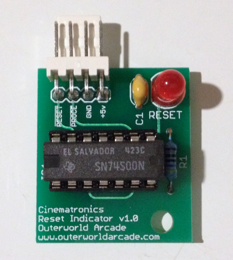
The Cinematronics Reset Indicator PCB adds the reset LED functionality to older Cinematronics and Vectorbeam CPUs.
In a working PCB, the reset indicator should light briefly when power is applied to the board. Afterward the indicator should remain off until power is removed and a very short flash may be seen. The LED gives a visual sign that the board is working correctly and that a vector monitor can be connected to the board.
In a board that is not working correctly, the indicator will remain lit. If a vector monitor is attached to a board in this state, the monitor will draw too much power from the game's power supply, causing its circuit breakers to trip after a second or two.
Videos
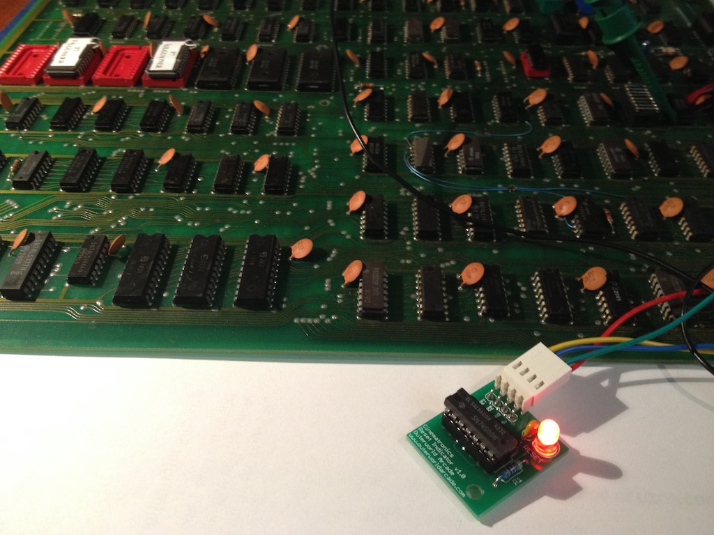
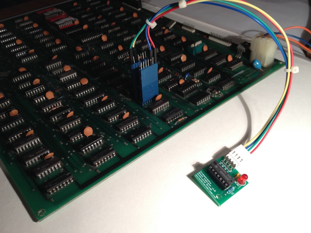
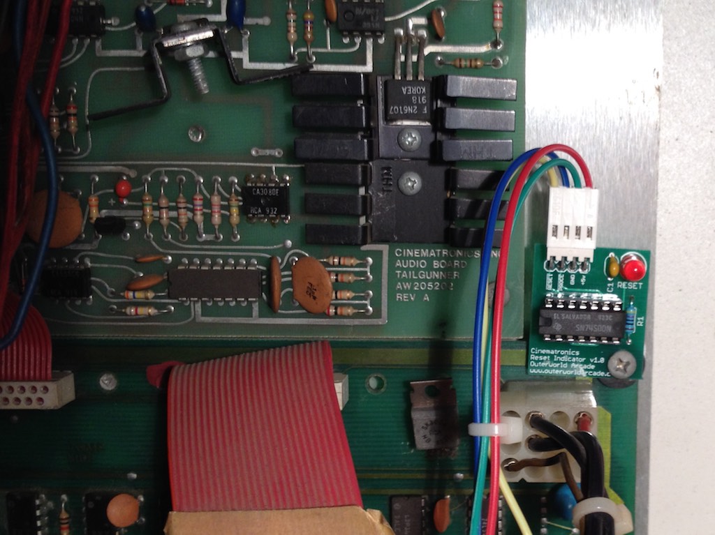
The Cinematronics Reset Indicator PCB attached to a Tailgunner (Rev. B) CCPU via a 14-pin Pomona 5114 test clip.
Below is a short video of a first test of the Reset Indicator PCB. The board was hooked up to a working Star Castle board and shows both functioning identically: a brief flash of the LED when power is applied to the CPU.
Package Contents
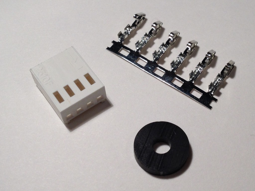
- (1) Reset Indicator PCB
- (1) 4-pin connector housing
- (6) pins - 4 pins & 2 spares
- (1) Rubber Washer
Connections Pin-out
The Cinematronics Reset Indicator PCB receives power and signals from the CCPU via four connections to the 74LS107 at C8.
|
Connecting Reset Indicator PCB to Cinematronics CPU (CCPU) |
||||
|---|---|---|---|---|
| To Reset Indicator PCB | <----> | To Cinematronics CPU | ||
| Pin # | Purpose | Wire Color | Pin # | Chip Location |
| 1 | RESET | Yellow | 5 | C8 |
| 2 | PROCEED | Blue | 12 | C8 |
| 3 | GND | Green | 7 | C8 |
| 4 | +5v | Red | 14 | C8 |
Installation Overview
For a temporary installation, connections to the CCPU can be made via a 14-pin test clip (such as a Pomona 5114) or a set of four miniature clip test leads.
For a permanent installation wires can be soldered to the chip's pins on the back of the board. This permanent installation is still easily reversible.
Connection to the RESET Indicator PCB can be done by crimping four of the supplied pins to wires (AWG 24-28) and installing them in the connector housing. The Platinum Tools 16801C, is one inexpensive tool that can be used to make these crimps. If you are connecting to a test clip and want to avoid crimping pins, 12"(300mm) Female/Female jumper wires can be used and simply slide onto the male pins on the test clip and the Reset Indicator PCB. An example of these wires can be found at Adafruit.
The indicator board can be secured to the CCPU board using the mounting screw in the upper right corner of the CCPU. An included rubber washer should be added between the two boards to prevent any contact between them.
If the CCPU needs repairs, the Reset Indicator PCB should be removed from the CCPU at the connector, so that it doesn't interfere with any exorcisor signatures. Leaving soldered wires attached to the CCPU should have no effect on the signatures.
Ordering Information
Availability (3/2024): In stock. Please contact me to purchase a board.